


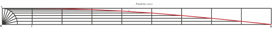
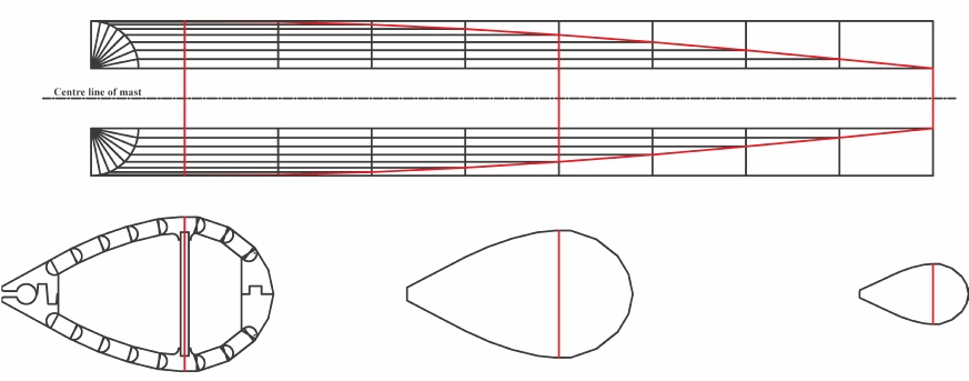
In the sketch above, the line AB is the amount of taper from hounds to top of mast, and CD is the length from hounds to top. At B, draw a quadrant with radius AB, and split it into equal segments, in this case 8. Similarly, break the line CD into 8 equal sectors. Starting at the highest sector, project a horizontal line to meet the first vertical line (at C), then repeat for each line in the quadrant to successive vertical lines. Link the intersection points as shown by the red line and Viola! a parabola. By mirroring this diagram as shown below, it is simple (in a CADD system) to scale a section of the mast for each intersected point on the parabola. The sketch below shows a simplified version of this. The red line in each section is the same length as the red line above between the two parabola lines.
From the full CADD drawings of these sections, I determined the width of every strip at every sector line, and, having built a exactly flat and straight assembly table, I marked the widths onto pairs of strips and planed them to the parabolic curve with a spoke-shave. (This took patience!)
From the same section drawings, I designed supporting formers to aid assembly, and had these CNC machined by Royal Wood (https://www.devoncncroutingservices.co.uk). What a fabulous resource to have close by!
The mast was initially assembled in two halves, and so I drew the formers to mesh so that not only would the strips be held together for each half, but also the same outer supports mesh to compress the two halves together. Confused? See the photos on the next page!